COMPLYING WITH ICH STABILITY GUIDELINES FOR TEMPERATURE AND HUMIDITY
By Clay Hile (Parameter Generation & Control, Inc.) © & Jeffrey Plugis (EdgeTech)
![]() On the surface, providing a specified humidity and temperature for stability testing may appear easier to achieve than the ±5% RH and ±2°C ICH guidelines would seem to indicate. The ability to control humidity at ±2% does not mean that you are safely within the ±5% RH tolerance dictated by the ICH (International Council for Harmonisation) and WHO guidelines.
On the surface, providing a specified humidity and temperature for stability testing may appear easier to achieve than the ±5% RH and ±2°C ICH guidelines would seem to indicate. The ability to control humidity at ±2% does not mean that you are safely within the ±5% RH tolerance dictated by the ICH (International Council for Harmonisation) and WHO guidelines.
What is Stability Testing?
Stability testing is a critical process that helps us understand how pharmaceutical products behave under various environmental stressors such as temperature, humidity, and light. This evaluation is pivotal in predicting the product’s shelf life, ensuring its safety, efficacy, and quality over time. The data derived from these tests are crucial for regulatory approvals, establishing storage conditions, and determining expiration dates.
Conducted primarily during clinical trial phases, stability testing continues throughout the product lifecycle and must follow specific ICH guidelines. The next section will delve into what these ICH stability guidelines are and why these guidelines are so important.
WHAT ARE ICH GUIDELINES?
The ICH is a committee consisting of representatives from various countries that seek to provide a unified standard within the pharmaceutical industry. The representatives, for example, are affiliated with the FDA, EMA and other drug regulatory agencies. These ICH guidelines help establish scientific and technical requirements for pharmaceutical product development and storage, ensuring their quality, safety, and efficacy over time.
Specifically, the ICH stability guidelines, known as ICH Q1A(R2), provide a comprehensive framework for assessing the stability of pharmaceutical products. This includes defining how long a product maintains its intended identity, strength, quality, and purity under specified storage conditions. Paired with WHO guidelines, ICH guidelines are crucial for identifying potential risks during stability storage, thereby safeguarding public health by ensuring that medicines remain effective and safe throughout their shelf life.
The Climatic Zones for ICH Stability
The ICH stability guidelines categorize the world into specific climatic zones, each defined by unique temperature and humidity conditions to simulate the environments where pharmaceutical products will be marketed. These zones are critical for determining appropriate storage and testing conditions to ensure product stability. The zones range from temperate to hot/humid conditions, each designated with specific temperature and humidity settings to guide stability studies.
For a general breakdown of these zones, please view the chart below.
| Climatic Zone | Climate Definition | Temperature | Relative Humidity | Geographic Areas |
| I | Temperate Zone | 21°C | 45% RH | Southern Canada, Europe, parts of Russia |
| II | Mediterranean/Subtropical Zone | 25°C | 60% RH | Mediterranean region, parts of Australia, southern USA |
| III | Hot/Dry Zone | 30°C | 35% RH | North Africa, Middle East, desert areas in the USA |
| IVa | Hot Humid/Tropical Zone | 30°C | 65% RH | Southeast Asia, Central Africa, parts of South America |
| IVb | Hot/Higher Humidity Zone | 30°C | 75% RH | Regions near the equator, dense rainforest areas |
Other Parameters to Consider with ICH Stability
The ability to produce a recording, display, or printout that is within a specified tolerance, based on ICH stability guidelines, may not be a demanding challenge, but this is only one of three parameters that should be considered. The display or recording is typically connected to one relative humidity sensor and specifically monitors the conditions at that single location in your room, chamber, or section of ductwork. The information from this sensor indicates the control constancy of the conditioner/controller system but it does not provide information on the conditions in other areas of the conditioned space.
In order to fully determine the true ICH conditions for the test or process environment the following parameters must be considered:
- Control Constancy – The ability of the conditioner and controller to maintain a constant control at the control sensor location
- Uniformity – stratification throughout the conditioned space caused by insufficient air flow, heat or moisture loads within the space, or leakage to or from an adjacent space
- Sensor Accuracy – calibration uncertainty of both the temperature and relative humidity sensors
For example, consider a targeted condition of 25°C ±2°/60% RH ±5% where the recording device may indicate a relative humidity control of +2%. Instead of being well within the required specification, it is quite possible that the requirement is not being met when the uniformity and sensor accuracy factors are included with the control constancy. A more comprehensive determination of test conditions can be achieved by considering the following:
- The best solid-state relative humidity sensors on the market today have an accuracy of +1% (when properly calibrated). In most cases, ±2% is more realistic.
- Depending on airflow and heat load location within a room, a relative humidity gradient of +1% to +6% could be expected.
- Add the above to the previously indicated control cycle (±2%) and the net total uncertainty, at any location a test is being performed could be anywhere from +4% to +9% or more.
To obtain the true required ICH conditions, a chamber or room must be designed with all three aspects of condition deviation in mind.
Single Point Constancy (control)
This is the amount of cycling or deviation from set point one would expect from the control sensor’s location. Within this category, account must be taken for conditioner/controller cycling, day/night and seasonal cycling, and sudden load changes (machinery or lights turning on or off, door openings, etc.). This aspect is dependent on the capability of the conditioning equipment and its controls.
Short-term conditioner control can be assessed when there are no load changes within the controlled area. Conditioner cycling includes refrigeration, heaters, and humidity/dehumidification cycles. Day/night, seasonal, and load cycling all involve an increase or decrease in sensible and latent loads that affects the long-term stability of the conditioned area. Ambient-driven change can be minimized with appropriate insulation and an adequate vapor barrier.
A conditioning system must be designed to handle the maximum anticipated latent and sensible loads. The source of most latent loads comes from, leakage, product, and door openings. Sensible loads come from lighting, equipment, leakage, and door openings. The system must be able to maintain control while the heat loads vary throughout daily and seasonal cycles.
Because relative humidity is temperature dependent, precise air temperature control is required for close relative humidity control. If moisture content stays constant at a 16.7°C dew point, but the air temperature is cycling ±1.0°C at 25°, the relative humidity is fluctuating between 56.5% and 63.7%. A small ±0.2°C air temperature cycle will cause a relative humidity cycle of more that 0.5% ASHRAE 1993).
Uniformity
Uniformity deals with the point-to-point differences of temperature and humidity across an entire conditioned area. Some of the major influences affecting uniformity include: total heat load (sensible and latent), load location, control sensor location, air distribution, volume of air exchanged, proper insulation and vapor barriers.
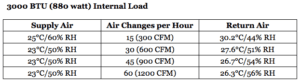
Total heat load (lights, equipment, people, and gain or loss through walls and ductwork) is the most important item affecting uniformity. If there were absolutely no load within the conditioned space, then uniformity would be easily handled, however this is not practical. For example: a 12’ x 10’ x 10’ room (1,200 cubic feet) with equipment, moving 600 CFM (30 air changes per hour) and a 3,000 BTU (880 watts) load has a temperature difference from supply to return of 2.6°C. If air is supplied at 25°C/60% RH and assuming there is no change in moisture content, then air is returned at 27.6°C/51% RH. Increasing total airflow or decreasing load can reduce this difference. At higher humidities, this same change in air temperature has a greater effect on the relative humidity.
The total volume of air exchanged is an important consideration when designing the distribution system and minimizing the effects of heat loads. Depending on the processes and internal load, 25 to 45 air changes per hour is a good target.
Load placement is also an important factor. If possible, it is best to locate loads as close to a return duct as possible to avoid disturbing the rest of the conditioned space. Load location should also influence the placement of the control sensors. Control sensors should not be located down stream of major load producers or in the return duct(s).
Air distribution should be uniform across the conditioned space. Typically, ceiling supplies and returns that pick up near the floor and around the periphery of the conditioned space are recommended (TAPPI TIS 018-7 1982). A design with both ceiling supplies and returns should be avoided. Applying the proper insulation and vapor barriers to the room and ductwork are very important depending on the conditions in the adjacent spaces. The importance of proper ductwork cannot be over emphasized. Due to the increased air velocity in the duct, the effect of a hole/leak in the ductwork is much greater than the same size hole in the chamber.
Avoiding outside walls, windows, and drop-ceilings are also helpful as these typically are greater heat loads than interior spaces.
Sensor Accuracy
There are both temperature and humidity sensors employed that need to be considered. Temperature sensors are typically far more accurate and generally easier to calibrate than humidity sensors. Using standard practices, one can typically obtain a ±0.1°C accuracy for the temperature sensor. Humidity measurement therefore becomes the primary area of concern.
Most humidity sensors on the market today have a claimed accuracy of +1% throughout a slightly narrowed range (i.e.: 20-80%RH). This is the best that one could expect from a new sensor, operating under moderate conditions. When choosing a humidity sensor, the accuracy specification must be validated over the entire expected range of operation. For example, if procedure calls to cycle temperature and humidity, one must ensure that the humidity sensor is properly temperature-compensated for the anticipated cycling range and that its accuracy does not shift as a function of temperature. Most humidity sensors lose accuracy above 80% relative humidity.
Relative humidity sensors must be calibrated regularly as they will drift over time. Calibration intervals will vary based on the type of sensor and the conditions of operation (temp. humidity range, cleanliness of atmosphere, concentration of various chemicals, etc). Typically, a one-year calibration interval is sufficient and should be considered the maximum. Specific intervals will be dictated by the application and it is best to start conservatively (i.e.: 6 months) and adjust later as appropriate. Confirm that the sensor calibration covers your operating range and is traceable to N.I.S.T. with supporting documentation on the calibration of the instrumentation.
Traceability means that the instrument has been calibrated against a primary or transfer standard. Most sensors are supplied with a calibration report (Certificate of Calibration) showing the accuracy at the time of manufacture, which does not truly reflect the way the instrument will perform in the field (Wiederhold 1997). The accuracy of the controller or adjustments made in the circuitry down stream of the sensor can affect the accuracy of the readout. One-way to avoid these errors is to field (in situ) calibrate the control sensor with a transfer standard while the system is in operation. This would be done using a suitable transfer standard such as a chilled mirror hygrometer.
ENSURE YOU ARE COMPLYING WITH ICH GUIDELINES
Obtaining specific temperature and humidity conditions based on the ICH stability guidelines can be a difficult task, but not an impossible one. If all the factors that affect environmental conditions are taken into consideration, the goal is certainly achievable. Some of the key points to remember are:
- Employ a conditioning system with tight single point control.
- Whatever system is obtained, make certain that it has the capacity to handle the internal and external heat load and has sufficient air handling capability to assist in enhancing uniformity.
- Use a relative humidity sensor suitable to your application; be sure that it is positioned properly and is calibrated routinely.
- Be mindful of the influences of heat loads on a conditioned space and try to minimize them.
- The conditioned space and ductwork must be well insulated with an uninterrupted vapor barrier.
If the above items are addressed, most of the problems associated with providing a conditioned space with precise temperature and humidity specifications will be eliminated and compliance with ICH stability guidelines should be met.
ICH Stability Conditions FAQs
What are ICH Stability Conditions?
ICH stability conditions refer to the specific environmental parameters (temperature, humidity) under which pharmaceutical products should be tested to ensure their shelf life and stability across different climatic zones worldwide.
Why are ICH Stability Conditions important?
ICH stability conditions are crucial for ensuring that pharmaceuticals maintain their efficacy, safety, and quality over time, regardless of the environmental stresses they might encounter in various global markets.
What is the purpose of accelerated stability testing?
Accelerated stability testing under ICH guidelines aims to speed up the aging process of pharmaceuticals, allowing researchers to predict their long-term stability in a shorter time frame.
Can ICH Stability Conditions affect product packaging?
Yes, the choice of packaging materials and designs can be influenced by stability testing results, ensuring that the packaging provides adequate protection against environmental conditions specified in ICH guidelines.
References
ASHRAE (American Society of Heating, Refrigeration and Air Conditioning Engineers) Handbook – Fundamentals, 1993, Chapter 6 – Psychrometrics
TAPPI (Technical Association of the Pulp and Paper Industry) TIS 018-7, “Paper Test Rooms: Design Considerations”, 1982
TAPPI T402 om-88, “Standard Conditioning and Testing Atmospheres for Paper, Board, Pulp Handsheets, and Related Products”, 1988
Wiederhold, Pieter R., “Water Vapor Measurement – Methods and Instrumentation”, 1997, Chapter 10 – Calibration