TAPPI STANDARDS & IDEAL CRITERIA FOR HUMIDITY TESTING CONDITIONS
by Clay Hile, Parameter Generation & Control, Inc.
Providing a specified humidity and temperature for testing or process control can be difficult in most settings and reaching the TAPPI (Technical Association of the Pulp and Paper Industry) standards with a prescribed testing atmosphere of 23°C +1°/50% RH ±2% can be close to impossible. Even TAPPI acknowledges, “the required relative humidity and temperature are difficult to achieve, and therefore careful attention must be given to the design, evaluation, and maintenance of the standard room” (TAPPI T 402 om-88 1988).
The ability to produce a recording, display, or printout that is within a specified tolerance can be a challenge, but this is only one of three parameters that should be considered. The display or recording is typically connected to one sensor and specifically monitors what is happening at that one location in your room, chamber, or section of ductwork. The information from this sensor indicates the control constancy of the conditioner/controller system but it does not provide information on the conditions in various areas of the conditioned space.
In order to fully comprehend the true conditions for the test or process environment the following parameters must be properly considered:
- Control Constancy – The ability of the conditioner and controller to maintain a constant control at the control sensor location
- Sensor Accuracy – calibration uncertainty of both the temperature and humidity sensors
- Uniformity – gradients throughout the conditioned space caused by poor air flow, heat or moisture loads within the space, or leakage to or from an adjacent space
For example, if the targeted condition is 23°C ±1°/50% RH ±2% and the recording device indicates a relative humidity control of +2%; instead of being within the required specification, it is certain that the requirement is not being met when uniformity and sensor accuracy are added to the control constancy. A more accurate determination of test conditions can be achieved by considering:
- The best humidity sensors on the market today typically have an accuracy of +1% (when calibrated)
- Depending on airflow and heat load location within a room, a uniformity of +1% to +6% could be expected
- These added to the indicated control cycle (±2%) will net a total uncertainty, at any location a test is being performed, of +4% to +9%
To obtain the required conditions necessary for TAPPI standards in humidity and temperature testing, a chamber or room must be designed with all three aspects of condition deviation in mind.
Single Point Constancy (control)
Within this category, account must be taken for conditioner/controller cycling, day/night and seasonal cycling, and sudden load changes (machinery or turning lights on or off, door openings). This portion is dependent on the capability of conditioning equipment and controls.
Short-term conditioner control can be assessed when there are no load changes within the controlled area. Conditioner cycling includes refrigeration, heaters, and humidity/dehumidification cycles. Day/night, seasonal, and load cycling all involve an increase or decrease in sensible and latent loads and affect the longterm stability of the conditioned area. Ambient driven change can be minimized with appropriate insulation, good vapor barrier, and proper handling of make-up air.
A conditioning system must be designed to handle the maximum anticipated latent and sensible loads. The source of most latent loads comes from people, leakage, sinks, and fresh air make-up. Sensible loads come from lighting, equipment, people, leakage, and make-up air. The system must be able to stay in control while the heat loads vary throughout daily and seasonable cycles.
Precise air temperature control is required for close relative humidity control. If moisture content stays constant at a 12°C dew point, but the air temperature is cycling ±1.0°C, the relative humidity is fluctuating between 47% and 53%. A small ±0.2°C air temperature cycle will cause a relative humidity cycle of more that 0.5% (ASHRAE 1993).
Sensor Accuracy
Temperature sensors are typically much more accurate and easier to calibrate than humidity sensors. Since it is fairly easy to obtain a ±0.1°C accuracy for the temperature sensor, humidity measurement is the primary concern in this area.
Most humidity sensors on the market today have an accuracy specification of +1%. This is the best that can be expected from a new sensor that is operating under moderate conditions. When choosing a humidity sensor, the accuracy specification should be checked over the entire range of expected operation. For example, if there are plans to cycle temperature and humidity, ensure that the humidity sensor is temperature compensated for the anticipated cycling range and that its accuracy does not shift with temperature. Most humidity sensors lose accuracy above 85% to 90% relative humidity.
Be sure to calibrate the sensors routinely for humidity sensors will drift over time. Calibration intervals will vary based on the type of sensor and the conditions of operation (temp. humidity range, cleanliness of atmosphere, concentration of various chemicals). Typically a one-year calibration interval is sufficient. Confirm that the calibration covers your operating range and is traceable to N.I.S.T. (National Institute of Science & Technology) and ask for documentation on the calibration instrumentation.
Traceability means that the instrument has been calibrated against a primary or transfer standard. Most sensors are supplied with a calibration report showing the accuracy at the time of manufacture, which does not truly reflect the way the instrument will perform in the field (Wiederhold 1997). The accuracy of the controller or adjustments made in the circuitry down stream of the sensor can affect the accuracy of the readout. One way to avoid these errors are to field calibrate the control sensor with a transfer standard while the system is in operation.
Uniformity
Uniformity deals with the point-to-point differences of temperature and humidity across an entire conditioned area. Some of the major items that affect uniformity include: total heat (sensible and latent) load, load location, control sensor location, air distribution, volume of air moved, proper insulation and vapor barriers.
Total heat load (lights, equipment, people, infiltration through walls and ductwork, and make-up air) is the most important item affecting uniformity. If there were absolutely no load within the conditioned space, then uniformity would be easily handled. A 12’ x 10’ x 10’ room (1,200 cubic feet) with equipment, moving 600 CFM (30 air changes per hour) and a 3,000 BTU (880 watts) load has a temperature difference from supply to return of 2.6°C. If air is supplied at 23°C/50% RH and assuming there is no change in moisture content, than air is returned at 25.6°C/43% RH. Increasing airflow, or decreasing load can reduce this difference.
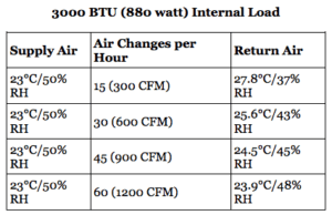
The total volume of air moved is an important consideration when designing the distribution system and minimizing the effects of heat loads. Depending on the processes and internal load, 25 to 45 air changes per hour is a good target. TAPPI recommends 15 to 30 air changes per hour (TAPPI TIS 018-7 1982), and that could still be insufficient depending on the amount of internal load. Load location is also an important factor. If possible, it is best to locate loads as close to a return duct as possible to avoid affecting the rest of the conditioned space. Load location should also influence the location of the control sensors. Control sensors should not be located down stream of major load producers or in the return duct.
Air distribution should be uniform across the conditioned space. Typically, ceiling supplies and returns that pick up near the floor around the periphery of the conditioned space are recommended (TAPPI TIS 018-7 1982). A design with both ceiling supplies and returns should be avoided.
Applying the proper insulation and vapor barriers to the room and ductwork are very important depending on the conditions in the adjacent spaces. The importance of proper ductwork cannot be over emphasized. Due to the increased air velocity in the duct, the effect of a hole in the ductwork is much greater than the same size hole in the chamber. Avoiding outside walls, windows, and drop ceilings are also helpful.
Conclusion
Obtaining your specified temperature and humidity conditions can be a difficult task, but not an impossible one. If all the factors that affect environmental conditions are taken into consideration, the goal is certainly achievable. Some of the key points to remember are:
- Purchase a conditioning system with a tight single point control.
- Whichever system is obtained, be sure that it has the capacity to handle the internal heat load and has sufficient air handling capability to assist in enhancing uniformity.
- Buy a sensor suitable to your application; be sure that it is positioned properly and is calibrated routinely.
- Be mindful of the influences of heat loads on a conditioned space and try to minimize them.
- The conditioned space and ductwork must be well insulated with an uninterrupted vapor barrier.
If the above items are given serious consideration, the problems of providing a conditioned space with precise temperature and humidity specification will be much more easily resolved.
References
ASHRAE (American Society of Heating, Refrigeration and Air Conditioning Engineers) Handbook – Fundamentals, 1993, Chapter 6 – Psychrometrics
TAPPI (Technical Association of the Pulp and Paper Industry) TIS 018-7, “Paper Test Rooms: Design Considerations”, 1982
TAPPI T402 om-88, “Standard Conditioning and Testing Atmospheres for Paper, Board, Pulp Handsheets, and Related Products”, 1988
Wiederhold, Pieter R., “Water Vapor Measurement – Methods and Instrumentation”, 1997, Chapter 10 – Calibration